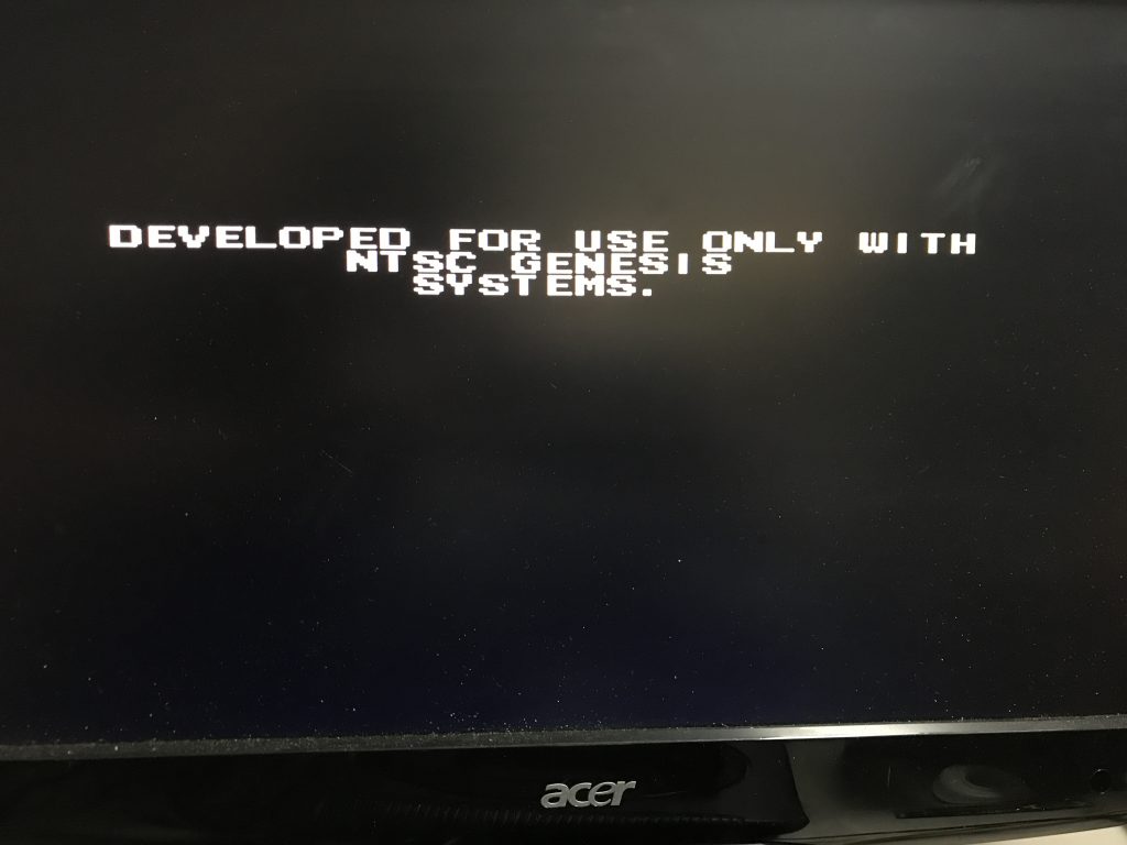
So I came a cross this game PCB without the shell and tried it. I then was greeted with a message I had never seen before; Developed for use only with NTSC Genesis systems. Okay that means that after 27 years it was finally time to mod my own SEGA…
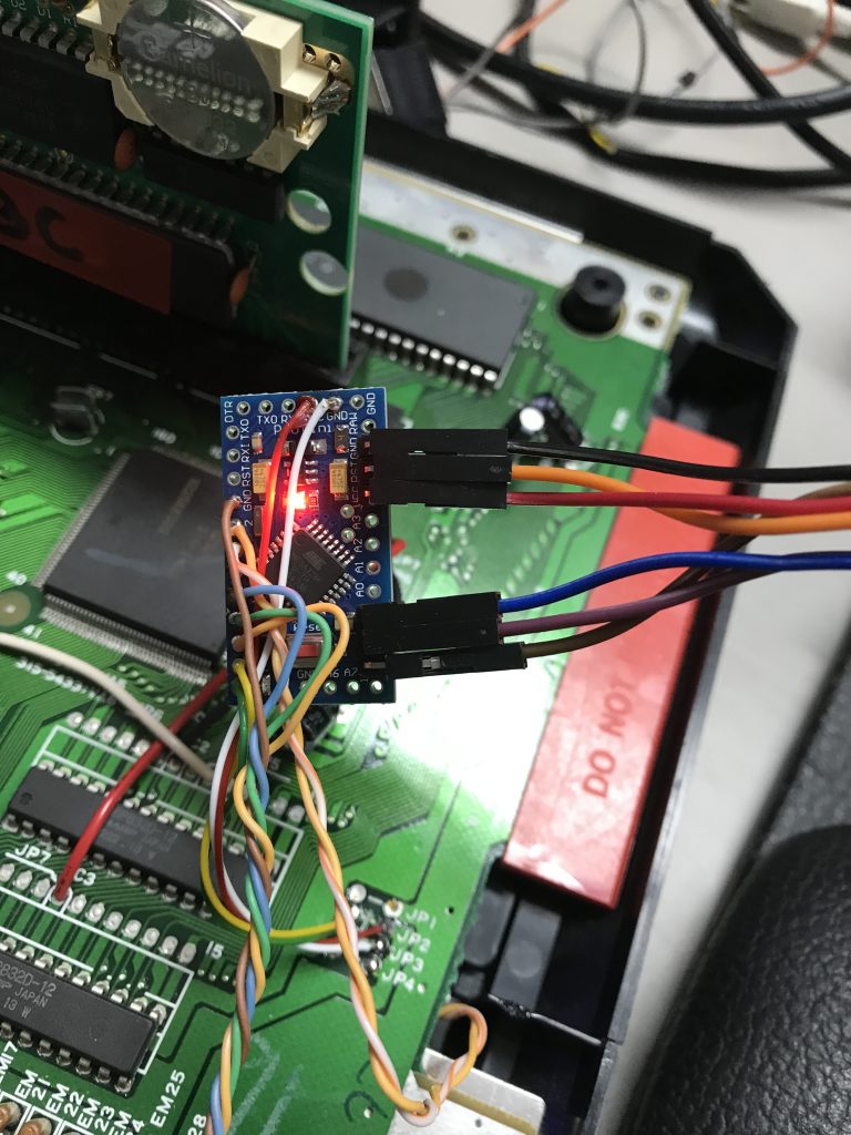
This is an easy mod and the part’s list is really short. I have used an Arduino Pro Mini, but any other version will work. Some wires and one RGB LED with the appropriate resistors. Yup, that’s all.
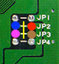
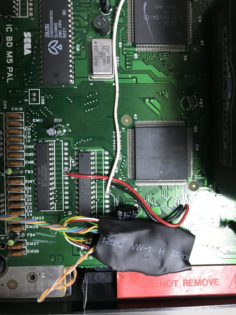
The region mod is very well described and there are a lot of websites (like @sega-16.com) you can find information on this. For my “IC BD M5 PAL” I cut the path on the main PCB between JP2 and JP3. If JP2 is connected to 5V the console will be in English, when connected to ground it will be in Japanese. If JP3 is connected to 5V the console will be in 60hz mode and when connected to ground in 50hz mode.
Connections to the Arduino:
RED = VCC
BROWN = GND
BLUE = Language selection
PURPLE = 50 / 60 Hz selection
I have done this mod before mostly because people wanted to get rid of the two black bars on the screen and speed up there PAL systems. And it is true, once you are used to play on 60Hz there is no going back 🙂 I still didn’t want to modify the outer shell of my MegaDrive so I decided to use te RESET button. If I press RESET twice it will change region. The power LED will then change from RED -> EUROPE to GREEN -> USA to BLUE -> Japan. If you long press the RESET it will save the current setting to the Arduino Eprom. If you just press RESET once it will act like the usual RESET.
To make this work we need to cut the path and solder 2 wires so we can control the RESET button with the Arduino.
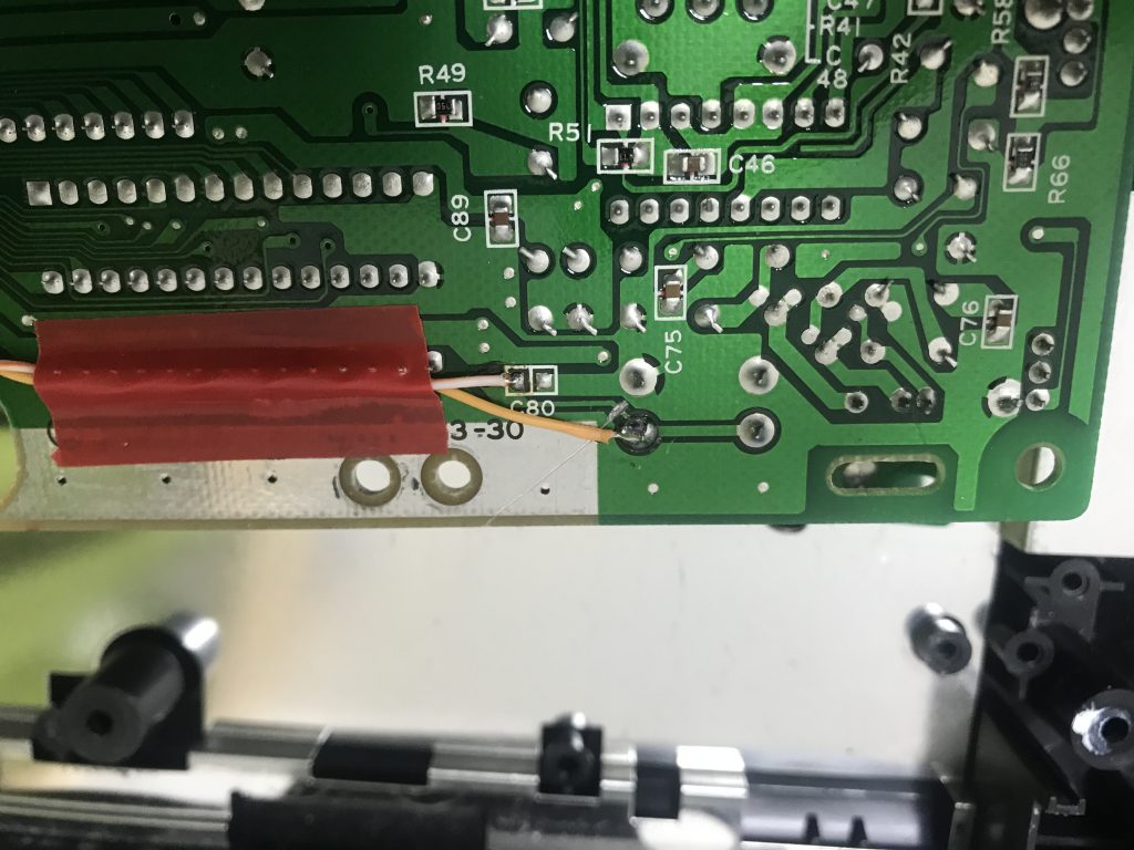
This is the underside of the main PCB. This is where you have to cut the path and solder 2 wires so we can control the RESET button with the Arduino. ( You really should not use this electrical tape! )
I suggest you program your Arduino with an external programmer so you loose the bootloader. This means the mod will instantly start without the 2 second boot loader delay.
A friend suggested I also add IGR (in game reset), but I didn’t see the use for it. If you do want IGR, I guess you could solder some extra wires to pin 6 and 9 of your first controller port. Pin 6 is used for Button A + Button B and pin 9 for START + C. The rest is up to you 😉
So where is everything connected? let’s have a look at the config in the source; (And yes it is verbose on purpose…)
*updated code here
#include <OneButton.h>                          //https://github.com/mathertel/OneButton
#include <Arduino.h>
#include <EEPROM.h>

// CONFIG // CONFIG // CONFIG // CONFIG //
const int address = 21;                          // EEPROM address we will write
const int HzPin =  9;                            // Pin connected to JP3 on the MegaDrive
const int LanguagePin = 8;                       // Pin connected to JP2 on the MegaDrive
const int HaltPin = 10;                          // Pin connected to pin 17 of 68K CPU (*not used yet)
const int Red_LED = 7;
const int Green_LED = 6;
const int Blue_LED = 5;
const int ButtonPin = 2;
const int ResetPin = 3;
// END CONFIG // END CONFIG // END CONFIG //

OneButton button(ButtonPin,                     // Pin connected to RESET switch
                 true,                          // Button is active LOW
                 true);                         // Enable internal pull-up resistor

int stateHZ;
int stateLANG;
int lastState;


void setup() {
  noInterrupts();
    lastState = EEPROM.read(address);                // Read the last state
      pinMode(LanguagePin, OUTPUT);                    // Set the digital pins as output
      pinMode(HzPin, OUTPUT);
    setState(lastState);
  interrupts();

  pinMode(ResetPin, OUTPUT);
  pinMode(Red_LED, OUTPUT);
  pinMode(Green_LED, OUTPUT);
  pinMode(Blue_LED, OUTPUT);

  //Serial.begin(9600);                              // //Serial for debug purpose
  //Serial.print("state = ");
  //Serial.println(lastState);

  button.attachDoubleClick(doublePress);            // Link the function to be called on event.
  button.attachLongPressStart(longPress);            // Link the function to be called on event.
  button.attachClick(shortPress);            // Link the function to be called on event.
  button.setPressTicks(3000);                       // Lenght of longPress in ms
}

void loop() {
  button.tick();                                    // Check the status of the button
  delay(10);                                        // A short wait between checking the button
} // loop

void shortPress() {                                // Reset the console
  digitalWrite(ResetPin, HIGH);
  delay(10);
  digitalWrite(ResetPin, LOW);
}

void doublePress() {                                // Get current state and switch to next
  State("next");
}

void longPress() {                                  // Save settings to eeprom
  State("save");
}

void State(char *var) {
  stateHZ = digitalRead(HzPin);                     // Check Current Hz state
  stateLANG = digitalRead(LanguagePin);             // Check Current Language state
  if (stateHZ == LOW && stateLANG == HIGH) {      // PAL
    if (var == "next") {
      setState(2);                                  //We change to 2 = USA
    }
    else {
      EEPROM.update(address, 1);                  // Save state to EEPROM
      CONFIRM();                                  // Blink LED to Confirm
      RGB_Color("RED");                       // Red Color Color
    }                                             // End Next or Save
  }                                               // End PAL
  else if (stateHZ == HIGH && stateLANG == HIGH) { // USA
    if (var == "next") {
      setState(3);                                  //We change to 3 = JAP
    }
    else {
      EEPROM.update(address, 2);                  // Save state to EEPROM
      CONFIRM();                                  // Blink LED to Confirm
      RGB_Color("GREEN");                         // Red Color Color
    }                                             // End Next or Save
  }                                               // End USA
  else if (stateHZ == HIGH && stateLANG == LOW) { // JAP
    if (var == "next") {
      setState(1);                                  //We change to 1 = PAL
    }
    else {
      EEPROM.update(address, 3);                  // Save state to EEPROM
      CONFIRM();                                  // Blink LED to Confirm
      RGB_Color("BLUE");                         // Red Color Color
    }                                             // End Next or Save
  }                                               // End JAP
}

void setState(int s) {
  switch (s) {
    case 1:                                         //PAL
      //HALT
        digitalWrite(HzPin, LOW);
        digitalWrite(LanguagePin, HIGH);
        RGB_Color("RED");                         // Red Color Color
        //Serial.println("PAL region set");
      break;
    case 2:                                         //USA
        digitalWrite(HzPin, HIGH);
        digitalWrite(LanguagePin, HIGH);
        RGB_Color("GREEN");                         // Green Color
        //Serial.println("USA region set");
      break;
    case 3:                                         //JAP
        digitalWrite(HzPin, HIGH);
        digitalWrite(LanguagePin, LOW);
        RGB_Color("BLUE");                         // Blue Color
        //Serial.println("JAP region set");
      break;
    default:                                          // Default is PAL
      digitalWrite(HzPin, LOW);
        digitalWrite(LanguagePin, HIGH);
        RGB_Color("RED");                         // Red Color Color
        //Serial.println("PAL region set");
      break;
  }
}

void CONFIRM() {
  for (int i = 0; i <= 2; i++) {
    RGB_Color("OFF");                         // All OFF
    delay(500);
    RGB_Color("WHITE");                   // White Color
    delay(500);
  }
}

void RGB_Color(char *color){
  int red; int green; int blue;
    if(color=="RED")            { red=130;  green=0;   blue=0;  }
    else if(color=="GREEN")     { red=0;    green=30;  blue=0;  }
    else if(color=="BLUE")      { red=0;    green=0;   blue=30; }
    else if(color=="WHITE")     { red=150;  green=30;  blue=30; }
    else if(color=="OFF")       { red=0;    green=0;   blue=0;  }
  analogWrite(Red_LED, red);
  analogWrite(Green_LED, green);
  analogWrite(Blue_LED, blue);
} -
Programming the Arduino with an USBASP -
Shrink wrap the Arduino when done

WROAUW SEGA! it seems my unknown PCB cart was a Genesis version of Jurassic Parc!