As mentioned before in my “cdj-1000-mk3-for-rekordbox” post I first connected the CDJ to Arduino. This post is all about reading the signal from the CDJ with the Arduino. Again this wouldn’t have been possible to do without the research of Andrei. https://github.com/DjFix/spi-spy The link to GitHub contains all information on CDJ 1000 mk3 SPI.
While I consider this an easy project, things could go wrong and you can damage your electronics! So do this project at your own risk!
Update
At the minimum you will need:
- at least one Cdj 1000 MK3
- at least one Arduino
- 5 wires (and the tools to solder them dUh)
If you want to use the Arduino for midi make sure it has an Atmel 32u4 like the Arduino Leonardo or Pro Micro. If you want to connect you Arduino to Rekordbox use the same trick I used in my project with the STM32 Discovery. Just name your device to a Pioneer DDJ. Like the Pioneer DDJ SX. You will have to do this in your Arduino IDE “boards.txt”.
The first google hit will give you VID en PID for DDJ-SX2 "PIONEER DDJ-SX2 2IN2OUT" vid="0x08E4" pid="0x01A2" And don’t forget to install the MIDI USB lIbrary.
Also make sure your Arduino is operating at 5 volt. This is because the CDJ is also working at 5 volt. if you use a 3.3 volt Arduino you will need a logic level shifter.
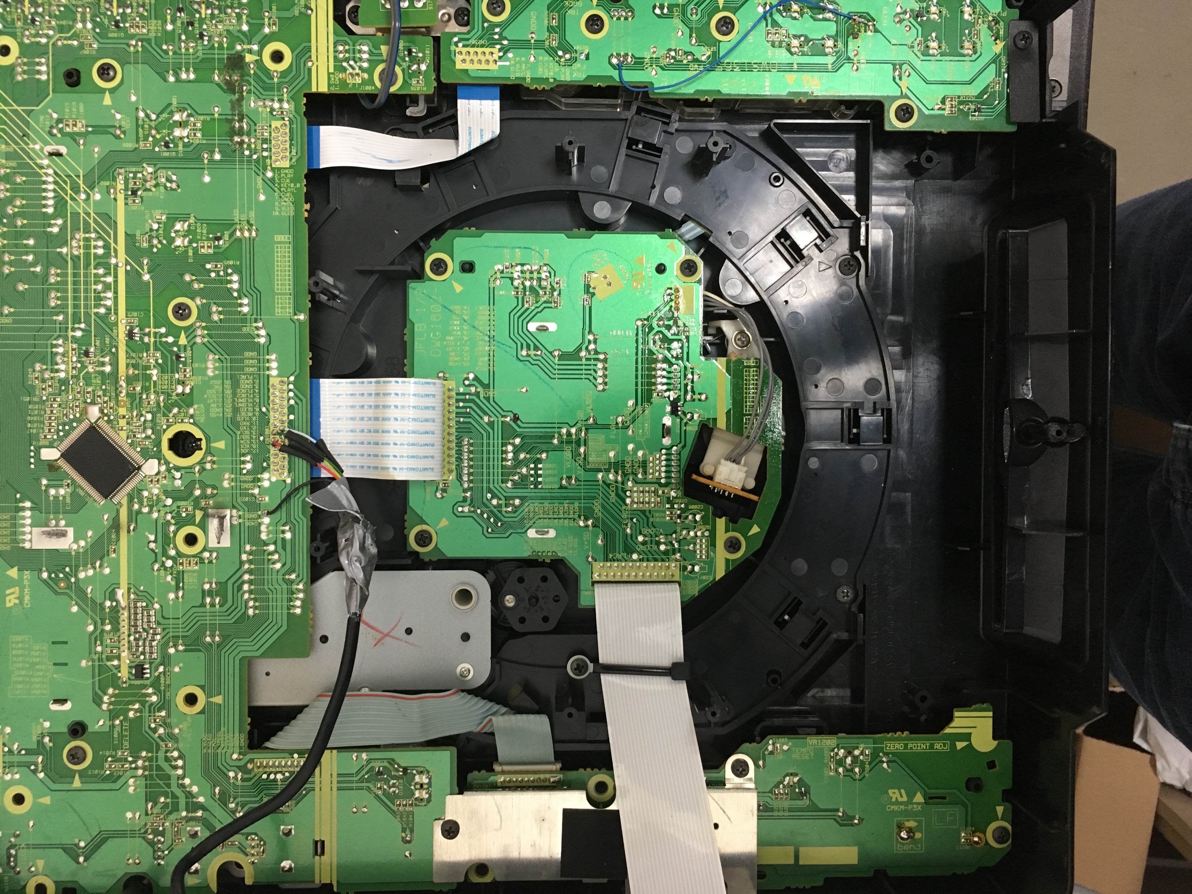
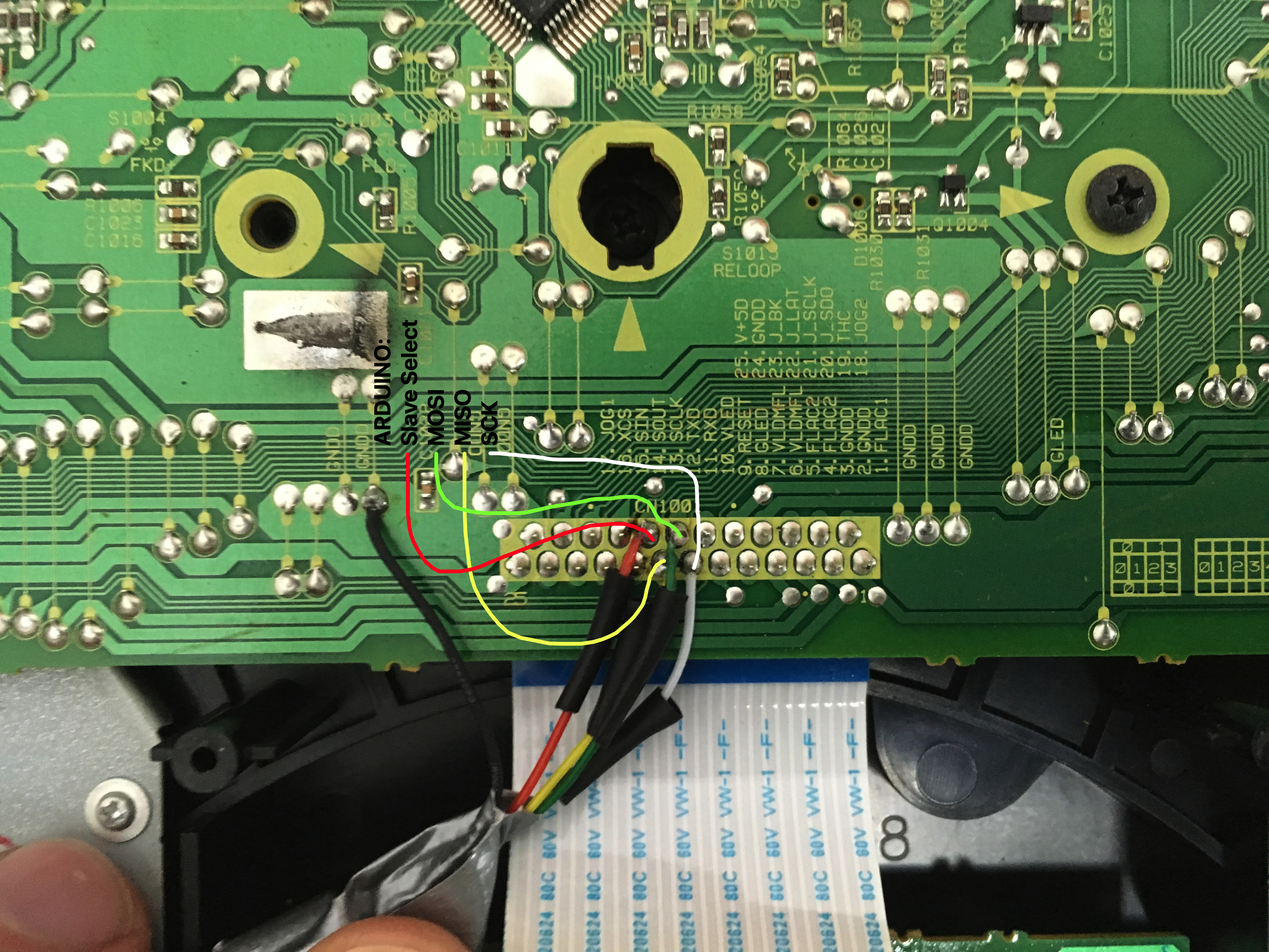
Don’t forget to disconnect your CDJ 1000 mainboard to prevent errors! Solder 5 wires to your front panel (see pictures) and connect these wires to your Arduino. You will need to look this up for your specific Arduino, not all Arduino’s use the same pins.
CDJ -> Arduino
13 CLOCK -> SCK
14 SOUT -> MOSI
15 SIN -> MISO
16 XCS -> SS
GND -> GND
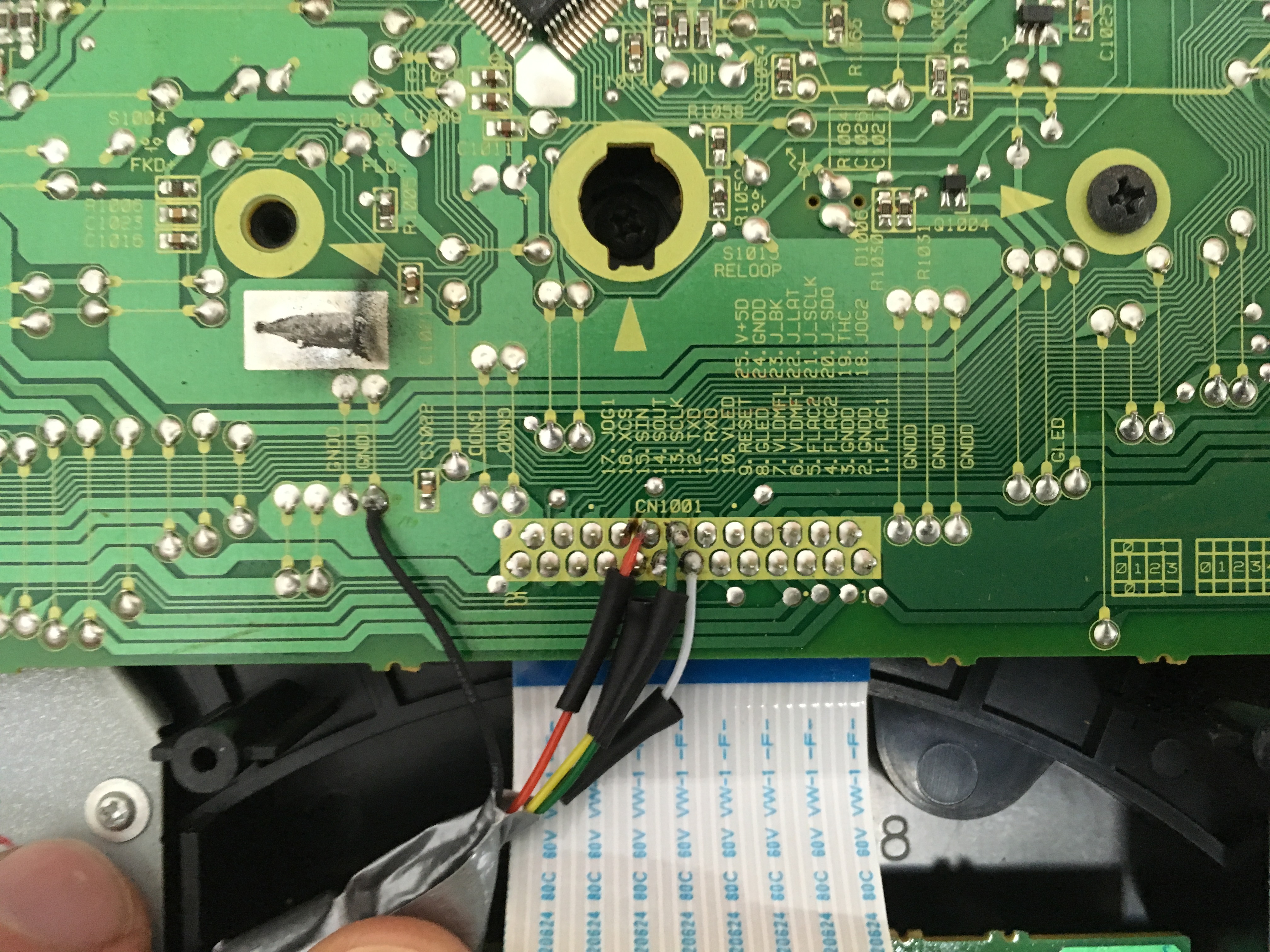
Before we look at the code, be sure to look at “Reverse_Engineering_Pioneer_CDJ-1000_serial_protocol.pdf” you downloaded from GitHub with the link at the beginning of this post.
When you scroll to page 4, you will see that the data from the CDJ is sent in 27 bytes. If we want to know if the PLAY button is pushed we will have to look at byte 14 bit 0.
Now when you have prepared your CDJ and Arduino with the code below your CDJ will give an error “E-8709” this is because the Arduino is not sending any information back to the CDJ. You will have to use the PDF mentioned and send the appropriate bytes to the CDJ. It is not necessary if you only want to receive data. The top unit will still send data if you press any of it’s buttons.
The code below is just to show that it is possible to connect and is far from optimized. I left out some parts to minimize the code and make it easier to understand. If you use this code or information be nice and give credit to everybody who spent time on this, thank you!
Now finally some code:
first let’s include the SPI library and add our variables
#include <SPI.h>
volatile byte data[27];
int i;

void setup() {
  pinMode(SCK,INPUT);
  pinMode(MOSI, INPUT);
  pinMode(MISO, OUTPUT);
  pinMode(SS, INPUT);
  digitalWrite(SS, HIGH); //disable

  //Serial for debugging
  Serial.begin(115200);
  while (!Serial) {
    ; // wait for serial port to connect. Needed for native USB
  }
  Serial.println("Slave initialized ...");
  Serial.println("");

  // turn on SPI in slave mode
  //SPCR |= bit (SPE);
  SPCR = (1 << SPE)|(0 << MSTR);
}
our setup is simple, we configure SPI and setup Serial for debugging
void ReadData(){
//read 27 bytes
for (i=0;i<=26;i++) {

//recieve bytes
while(!(SPSR & (1<<SPIF))); // waiting for a SPI transmission to complete
data[i] = SPDR;

//check if data is recieved correct byte 0 must be 1
if (data[0]!=1){ break; }

}//end read 27 bytes
}//end ReadData
Here is our main loop.
void loop() {
ReadData();

//if you want to debug you can use the following line
//to show what you have received from byte 14
//Serial.println(data[14]);


if (data[0]==1 && data[1]==16){
ShowByte14(); //Play Que Loop
ShowByte16(); //Track Search
}
}//end main loop
To keep the main loop a little cleaner I created a separate function for every byte.
void ShowByte14(){
if (data[14]==1){ Serial.println("Play");}
if(data[14]==2){ Serial.println("CUE");}
}//end show byte 14

void ShowByte16(){
if (data[16]==1){ Serial.println("Rec Mode");}
if (data[16]==2){ Serial.println("<< Track"); }
if (data[16]==4){ Serial.println(">> Track");}
if (data[16]==8){ Serial.println("<< Search"); }
if (data[16]==16){ Serial.println(">> Search");}
}//end show byte 16
Good luck and happy tinkering 🙂
Could you show us in a video how it works with the arduino.
we want to see how the cdplayer leds work and also how the central display of the cdplayer works
Hi Fercho, Sorry I have no intention to work on this project with Arduino. As I found out there are beter platforms to use like the STM32. Mainly because it has SPI DMA. I have said it before and I’ll say it again; if you want to know more go have a look at the CDJ new life project. There you can even download the source! -> https://github.com/djgreeb/CDJ-1000mk3_new_life_project
Awesome,
can you post the VOID SETUP ?
I tried to use the basic void setup setting
void setup(){
Serial.begin(9600);
SPI.begin();
}
But your code doesn’t work.
I tried to use your code on arduino MEGA and PRO MICRO too.
I will really thankfull if you post de void setup part.
I must have missed that, and nobody noticed before. I update the code but have not tested it.
hi,
how I can send data from arduino to cdj to power led when I use play and cue button?
I have do some test but I can rebuild the bynary value to send via arduino SPI.
Can you help me?
Thank’s
Hello, I do everything according to your description. Unfortunately, I have encountered a problem. Either your code does not work or I have a problem with SPI communication. I bought Ardruino proMicro. I understand that Ardruino is supposed to work in slave mode. The board does not have a dedicated SS pin. In master mode, we can easily select the pin and initialize it in the code. Do you know how this relates to slave mode? I have not found a solution to this problem on the Internet. I would be grateful for your help 🙂